I have an old pair of PSB Image 2B speakers I use on a mini stereo system out at my cabin. I did an upgrade on them by replacing the cheap electrolytic caps in the crossovers with some higher quality Dayton 5% audio-grade caps. The result was very noticeable and pleasing.
The tweeters on the 2Bs were made by Peerless and you can get very similar Peerless tweeters that will bolt right in from Parts Express and other places quite inexpensively. You might also still be able to get the "official replacement" tweeter from PSB (haven't checked to see if they're still carrying them) but I've heard they're 3 - 4 times as expensive as the replacement tweeters from PE. I don't want to put a lot more money into these speakers so I won't buy the OEM ones if they are even available but I'm willing to pay the $22 each to get a replacement from PE.
The Image 2Bs have a nominal impedance of 6 ohms (which I know doesn't mean much) and a minimum impedance of 4 ohms. The crossover frequency is 2.5 KHz.
There are two tweeter models available from PE that will bolt right in and there are 4 and 8 ohm versions of them both. I'm only interested in the highest quality model of the two models so that would be the Peerless BC25SC08 model. The question is, should I get the 4 ohm or 8 ohm version?
Here is the impedance curve for the Image 2Bs:
I am definitely no expert here but the way I figure it, when you get to say 5 KHz and above pretty much all of the impedance you're seeing is from the tweeter. Is that correct? And that impedance looks to be around 8 ohms. Correct? Where the speaker's impedance curve drops below 6 Ohm is down in the low frequencies where it's all woofer so my interpretation of that is it's the woofer that's driving the 4 ohm minimum impedance rating, not the tweeter. Is that correct?
Here are the impedance curves for the 8 ohm and then 4 ohm versions of the BC25SC08 tweeters/
BC25SC08-08
BC25SC08-04
Based on these three plots, I'm thinking the PSB OEM tweeter was an 8 ohm rated tweeter so the BC25SC08-08 is the correct one to replace it with.
Is my interpretation of the data correct?
The tweeters on the 2Bs were made by Peerless and you can get very similar Peerless tweeters that will bolt right in from Parts Express and other places quite inexpensively. You might also still be able to get the "official replacement" tweeter from PSB (haven't checked to see if they're still carrying them) but I've heard they're 3 - 4 times as expensive as the replacement tweeters from PE. I don't want to put a lot more money into these speakers so I won't buy the OEM ones if they are even available but I'm willing to pay the $22 each to get a replacement from PE.
The Image 2Bs have a nominal impedance of 6 ohms (which I know doesn't mean much) and a minimum impedance of 4 ohms. The crossover frequency is 2.5 KHz.
There are two tweeter models available from PE that will bolt right in and there are 4 and 8 ohm versions of them both. I'm only interested in the highest quality model of the two models so that would be the Peerless BC25SC08 model. The question is, should I get the 4 ohm or 8 ohm version?
Here is the impedance curve for the Image 2Bs:
I am definitely no expert here but the way I figure it, when you get to say 5 KHz and above pretty much all of the impedance you're seeing is from the tweeter. Is that correct? And that impedance looks to be around 8 ohms. Correct? Where the speaker's impedance curve drops below 6 Ohm is down in the low frequencies where it's all woofer so my interpretation of that is it's the woofer that's driving the 4 ohm minimum impedance rating, not the tweeter. Is that correct?
Here are the impedance curves for the 8 ohm and then 4 ohm versions of the BC25SC08 tweeters/
BC25SC08-08
An externally hosted image should be here but it was not working when we last tested it.
BC25SC08-04
An externally hosted image should be here but it was not working when we last tested it.
Based on these three plots, I'm thinking the PSB OEM tweeter was an 8 ohm rated tweeter so the BC25SC08-08 is the correct one to replace it with.
Is my interpretation of the data correct?
Last edited:
I just looked at the data simplistically, and compared the impedances at 10kHz in each of the three cases.
The approximate values, in order of appearance, are 7 ohm, 9 ohm and 4 ohm.
If the 7 ohm figure is being boosted by the presence of a series resistor, would that make the 9 ohm figure the least likely match?
Whatever, I agree that the only way to be sure is to see the crossover schematic.
The approximate values, in order of appearance, are 7 ohm, 9 ohm and 4 ohm.
If the 7 ohm figure is being boosted by the presence of a series resistor, would that make the 9 ohm figure the least likely match?
Whatever, I agree that the only way to be sure is to see the crossover schematic.
I don't have the speakers here so I can't draw a schematic and I can't find the schematic on the Internet. The best I can do is provide you with a picture of the crossover and tell you that the capacitors are 2.2 uF, 8.0 uF and 12 uF. There is one resistor in the crossover. The lettering on it appears to say "5W3R3".
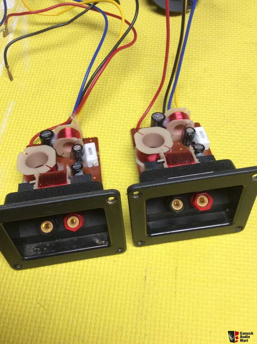
Are you able to make a guess as to what the crossover schematic looks like or at least deduce what tweeter would likely be closest with that information?
On my speakers, I replaced those electrolytic caps with 2.2, 8.2 and 12 uF Dayton 5% Audio Grades and it made a very nice improvement.
Are you able to make a guess as to what the crossover schematic looks like or at least deduce what tweeter would likely be closest with that information?
On my speakers, I replaced those electrolytic caps with 2.2, 8.2 and 12 uF Dayton 5% Audio Grades and it made a very nice improvement.
It would be a lot of guesswork what filter order and 2 smaller inductor values are to accurately solve for the problem. After some experimenting, I came up with this circuit that comes reasonably close to original impedance, but I can not say for certain.
Attachments

Last edited:
Lojzek, thank you so much for the work you did and your insights! I must admit that when I look at that schematic, I don't fully understand how it works or why it would be designed that way. I know the basics of how crossovers work with capacitors being high pass filters and inductors being low pass filters and I certainly know what a resistor does but I don't really understand why you'd put those inductors and the resistor where they are in that circuit. Are they there just to drain off some power going to the tweeter and get the impedance right where they want it and/or perhaps flatten the impedance curve at certain frequencies where there may be humps or dips? 
If someone could explain the theory behind this circuit and how it works it would be much appreciated (and interesting). TIA
If someone could explain the theory behind this circuit and how it works it would be much appreciated (and interesting). TIA
Lojzek has drawn a fourth order (24dB/octave) high pass (HP) filter.
If we look at the second order (12dB/octave) HP filter shown above, the capacitor blocks the low frequencies while passing the high frequencies. On its own, the capacitor would achieve only 6dB/octave. The inductor blocks the high frequencies and forces them to flow through the tweeter while bypassing any remaining low frequencies around the tweeter to increase the effectiveness of the HP filter to 12dB/octave.
By cascading two second order HP filters together as shown in Lojzek's schematic, we increase the rate of the HP filtering to 24dB/octave.
Now, what does the resistor do?
I'll let Lojzek explain that!
An externally hosted image should be here but it was not working when we last tested it.
If we look at the second order (12dB/octave) HP filter shown above, the capacitor blocks the low frequencies while passing the high frequencies. On its own, the capacitor would achieve only 6dB/octave. The inductor blocks the high frequencies and forces them to flow through the tweeter while bypassing any remaining low frequencies around the tweeter to increase the effectiveness of the HP filter to 12dB/octave.
By cascading two second order HP filters together as shown in Lojzek's schematic, we increase the rate of the HP filtering to 24dB/octave.
Now, what does the resistor do?
I'll let Lojzek explain that!
Last edited:

Could the 3.3 ohm resistor be in series with a 4 ohm tweeter to provide the necessary attenuation?There is no way one could use such high sensitivity tweeters without any resistor attenuation.
I'm thinking that would explain the ~7 ohm impedance as seen at 10kHz in the speaker's impedance curve.
Am I barking up the wrong tree?
The tweeters are both still working okay but they did have a reputation for failing prematurely. I've heard that swapping in a BC25SC08 series tweeter can yield a noticeable improvement and I thought that since they were inexpensive they'd be worth a try. I just don't know which version (4-ohm or 8-ohm) to get. I'm hoping it's the 4-ohm because obtaining the 8-ohm ones while still possible, is difficult. The 4-ohm ones are much more readily available.
I don't know if these pics can help you figure out what the schematic would look like but here are pictures of a crossover after I modified it in case they help. Unfortunately, you can't see all of the tracings on the underside of the PCB because of the capacitors but you can see quite a bit of it.
I will contact PSB tomorrow to see if they can/will supply me with a schematic for that crossover. Hopefully they can/will.
I will contact PSB tomorrow to see if they can/will supply me with a schematic for that crossover. Hopefully they can/will.
Attachments


.png)
.png)
Last edited:
Sorry Galu, I don't know. When I upgraded the caps I only photographed the XOs before I soldered off the wires to make sure I soldered them back onto the right places. I never looked to see what wires went where.
I didn't measure the DC resistance of the tweeters and I can't right now because they're at my cabin 600Km away. I was hoping to have a replacement set of tweeters in hand when I head out there in a couple weeks to open up...
I didn't measure the DC resistance of the tweeters and I can't right now because they're at my cabin 600Km away. I was hoping to have a replacement set of tweeters in hand when I head out there in a couple weeks to open up...
Last edited:
The inductor blocks the high frequencies and forces them to flow through the tweeter while bypassing any remaining low frequencies around the tweeter to increase the effectiveness of the HP filter to 12dB/octave.
Not entirely correct, as the coil passes low frequencies. As frequency increases, the resistance increases in the coil so that they no longer pass through the coil.
So- the cap blocks low freqs, and the coil shunts away low freqs. If the cap did not block the lower freqs, the coil would be seen by the amplifier as a dead short.
Wolf
I don't think our descriptions are at odds, Wolf, if we compare them carefully.
Actually, I prefer to think of the series LC circuit as a potential divider.
In a potential divider, the component with the larger opposition to the flow of current gets the larger share of the applied voltage.
The capacitor has the larger opposition to low frequencies so the low frequency voltages develop across the capacitor.
The inductor has the larger opposition to high frequencies so the high frequency voltages develop across the inductor.
So, if you want the series circuit to act as a high pass filter, you would connect the tweeter across the inductor where it will be driven by the high frequency voltages.
I think I get all this but what was the purpose of the resistor that Lojzek put in the coil shunt in that circuit schematic that he first postulated might be the schematic for my speaker's crossover?
It's interesting but today I looked at a fair number of off-the-shelf pre-fab 2-way 2.5 KHz XO frequency crossovers available from a number on-line vendors and none of them were like the crossovers PSB used in these speakers. None had 3 inductors, 3 capacitors and one resistor. Is this design that PSB is using in these speakers unusual or maybe a little more elaborate than what they use in most off-the-shelf pre-fab crossovers?
It's interesting but today I looked at a fair number of off-the-shelf pre-fab 2-way 2.5 KHz XO frequency crossovers available from a number on-line vendors and none of them were like the crossovers PSB used in these speakers. None had 3 inductors, 3 capacitors and one resistor. Is this design that PSB is using in these speakers unusual or maybe a little more elaborate than what they use in most off-the-shelf pre-fab crossovers?
- Home
- Loudspeakers
- Multi-Way
- Am I interpreting this information correctly? (Tweeter selection problem)