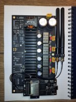
After asking for some feedback on my platform to easily prototype any of my future DIY audio project on Reddit, I started designing/building it and thought I could have a build log in case anyone is interested critiquing/reproduce any of it.
Streamer/Receiver:
Plate Amp/Digital crossover:
Streamer/Receiver:
- Software/Configuration
- [✔] APT-x Bluetooth
- [✔] 96KHz Pipewire Config
- [✔] I2S Slave config to Main DSP
- [✔] I2C Bus communication to Main DSP
- [✔] SPI Connection to OLED screen
- Schematics/PCB Design
- [95%] Parts selection
- [✔] I2S Over HDMI Driver
- [75%] Motherboard
- [25%] S/PDIF receiver: Still trying to decide between 3 ICs (CS8421, WM8804, DIX9211)
- Soldering/wiring
- Mechanical/CAD
- [✔] Modeling Rotary Encoder
- [✔] Modeling OLED Screen
Plate Amp/Digital crossover:
- Software/Configuration
- Schematics/PCB Design
- [✔] Parts Selection
- Soldering/wiring
- Mechanical/CAD
Last edited:
Adding the schematics PCB for the I2S over HDMI driver.
The reason why it is separated from the mother board is to


The reason why it is separated from the mother board is to
- Have more freedom placing the connectors on the enclosure
- stay below the 100mm soft size limit on JLCPCB
- potentially stack multiple if I wanted to have even more than 4 individual speaker enclosures
Good start! Will try to follow this! Good to see some elcaps on the supply. Only MLCCs in parallel is dangerous as any trace is an L and none of them have any resistance to dampen possible oscillations. Try K-sim from kemet where you can put specific parts in parallel and see how you can achieve the lowest impedance in the frequency region of your interest. And then add something to dampen as well.
That's very good advice thanks. I was about to order but now I'll take some time to ponder on this first. I didn't know about this simulator, it's very useful. I usually just blindly follow the datasheet recommendations but I know it's not always the best. I tried to have very low inductance from the Elecap to the MLCCs with wide pours, but I don't know how I would even estimate what is the inductance to test if things would start to oscillate. Any recommendations there ? (Using Kicad and I don't think it has a tool to do that).
What would be your recommendation to dampen? A resistor between the Elecap and MLCC or a snubber ?
What would be your recommendation to dampen? A resistor between the Elecap and MLCC or a snubber ?
Did a couple of tests for the front of the enclosure and pretty happy with the result. I think I will settle with a footprint of 150x140x75mm(WxDxH). Since it's 3D printed I was considering making the front slightly tiled upwards to make the screen more readable but not 100% sure about how it would look and it would reduce the internal volume. I guess it's something I can play next week when I have all the rear panel done.
Any recommendation for the best power inlet connector ? I have a couple IEC C14 with integrated fuses in my parts bin but they are quite bulky and are overkill in terms of current draw. Is it worth getting IEC C6 and skipping the fuse ? (I'm sure the Meanwell power supply has internal fuses anyway).
Since I want to be able to use WiFi I'm doing a plastic enclosure. The power supply is enclosed by a grounded metal cage. Does this overall design satisfy the "Double-Enclosure" safety criterion ? I'm not sure how to interpret this.
Last edited:
Hi,
Nice project!
For the dsp + 4ch amp maybe something like that would fit: TAS5548 + 2xTAS5162. There is also ADAU1452 but if only crossover is needed, it may be redundant. Or vice versa if you'd like ta have DAC and D-class amp with analog input.

(wifi module on the bottom is not required for the amp to work, there are 2xI2S and SPDIF inputs available thru ADAU1452)
Nice project!
For the dsp + 4ch amp maybe something like that would fit: TAS5548 + 2xTAS5162. There is also ADAU1452 but if only crossover is needed, it may be redundant. Or vice versa if you'd like ta have DAC and D-class amp with analog input.

(wifi module on the bottom is not required for the amp to work, there are 2xI2S and SPDIF inputs available thru ADAU1452)
That looks great! Too bad, the only thing I would miss is the HDMI input. One of the motivation behind this project is to avoid carrying up to 16 pairs of 14 awg wire so digital coms is a hard requirement. Also it's a good opportunity for me to practice analog circuits so I'll try to do it myself. I'm in a rental so it's not really an option to dig conduits in the walls and those big bundles of wire look bad.
However if it takes too many attempts to get something I'm satisfied with this is an amazing bailout alternative as I could just do the HDMI to i2s board and still have a working end product. Thanks for the suggestion!
However if it takes too many attempts to get something I'm satisfied with this is an amazing bailout alternative as I could just do the HDMI to i2s board and still have a working end product. Thanks for the suggestion!
Last edited:
- Home
- Design & Build
- Electronic Design
- [Build Log] Streamer, modular electronic crossover amplifier