My take on the choice of material for the suspension is that they wanted to maximize heat dissipation in a very open suspension design, hence copper. For hifi use this is probably a non issue so other materials can be used, PEEK is one good choice, another one is one sided copper/fr4 laminate since that could also provide the vc lead-in wires.
//Anders
//Anders
I never thought about copper as just heat dissipation, but it could be. It is glued directly to the aluminium dome. But I think it has be something more. Some people have made brass versions of 1175Hz horns, because of excellent qualities of brass. Brass is pretty close to copper-beryllium, maybe.
In the meanwhile, here are some JA6681B in action:
In the meanwhile, here are some JA6681B in action:
I think the main reason for the copper suspension was low hysteresis rather than heat dissipation.
S shape fingers perhaps to reduce reflections from dome to driver and back?
Which is why the Yamaha might be even better with a Be dome? Unlike the radians it seems that there is little there to stop the driver exploiting the benefits of Be.
Well, maybe a phase plug tweak
Will try and dig out a unit and post pics next couple days.
You will not find a company that will clone the design 1to 1. I measured the thickness of the copper/be fingers early in this thread but the thickness of each material layer and the copper composition is unknown.
I would say that the S Finger Design is smart and important but the material might not be crucial.
It might even work if the dome extends into a flat rim of which the S fingers are routed or punched out.
I would say that the S Finger Design is smart and important but the material might not be crucial.
It might even work if the dome extends into a flat rim of which the S fingers are routed or punched out.
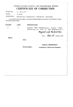
I find the can-do attitude in this thread uplifting. In case folks don't have it already, here's the Yamaguchi et al patent on the famed but short-lived Yamaha JA6681A diaphragm. I got this from a fellow DIYer years ago.
Trivia: Meyer Sound was the largest buyer of the JA6681A, which they used in their UPA-1A loudspeaker and 833 studio monitor. When they changed over to their own driver for the UPA-1P, Yamaha discontinued the JA6681A.
Good luck!
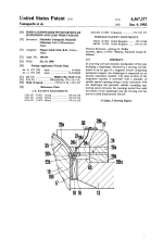
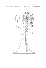
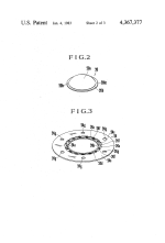
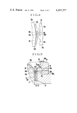
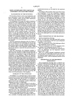
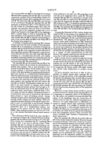
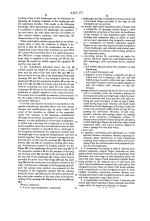
Trivia: Meyer Sound was the largest buyer of the JA6681A, which they used in their UPA-1A loudspeaker and 833 studio monitor. When they changed over to their own driver for the UPA-1P, Yamaha discontinued the JA6681A.
Good luck!


This is what I proposed earlier.
For a visual help I show the backside of my Emilar diaphragm.
Look at the rim the red line points to. If this was more extended out then the S-shape fingers could be routed out with a high speed Router.
Basically for a test a 75mm diaphragm could to be kinked right at 66mm. From the extending material beond the kink the s- fingers could be routed out. Then the voice coil of my phenolic diaphragm could be glued on to the diaphragm.
I have access to a top tool shop but sadly zero time.
Attachments
I manage our prototype workshop at work and have no problem doing high speed milling (90.000 RPM) with tools down to 0.2mm. CAD and CAM for this is no issue either if needed. Due to workload from paying projects nothing can be started until after the summer though.
//Anders
//Anders
I suggest using acetone to dissolve the glue (which is most likely epoxy) on a broken diaphragm, to reveal the different parts. Then use a photo scanner to scan the copper finger suspension to create a 2D image. 2D is all we need to reproduce the copper fingers. The image can be used in autocad or similar, to CNC the fingers. This can be ordered by any number of companies. Or for Bappe. 
A lidar scanner on an iphone or something more advanced can help to create the dome shape needed. The scanned dome needs to come from a somewhat complete diaphragm. The edge where the dome and the copper finger is glued to each other would be good to measure properly. Maybe acetone would be best to release a compete aluminium diaphragm from the rest of the asembly.
The black rings that clamp everything together should be easy enough to be recreated in 3D printer.
We also need some alminium metal shims to sandwich the outer part of the copper fingers.
I still think that copper is not needed. Back in 83 they did not have the materials of today.
If we punch the duralmin AlCuMg at once we get a shape like in the red drawing. The blue line indicates different foils that the dome with the rim can be glued to. Then the Aluminium with the foil can be routed at once.
Winding a coil is not rocket science either.
If we punch the duralmin AlCuMg at once we get a shape like in the red drawing. The blue line indicates different foils that the dome with the rim can be glued to. Then the Aluminium with the foil can be routed at once.
Winding a coil is not rocket science either.
Attachments
Guys I am serious we can do this.
The Punch Form needs to be done by metal erosion technik. That will cost a bit if we don't have a friend or relative that works in such a Business. The rest is mostly trial and error work to find the right foil and thickness of it on which the dome is glued on.
The duralmin foil is not very expensive either.
I have access to a press to which the negativ and positiv forms can be attached.
I could press 20 or 30 domes and send them to the one who dose the next stepp.....
5°Pierre, I tried to measure the straight section of the throat and I get 3 degrees on the drawing you posted, Do you happen to know if that is correct?
Time for a vacation in Sweden 😎Oh, and I have a laser scanner as well
//A
Concerning the hf weakness of the driver. I want to rid my JA6603 (identical motor) of its FE magnet and replace it with several pieces of same thickness evenly distributed Neodymium Magnets.
I am looking for the best way to get the magnet off without damaging the soft iron pieces.
I think I will stick copper in the air gap and use an angle grinder making a one inch deep groove in the middle of the magnet. Gently forcing big screwdrivers on opposing sites
into the groove should break the magnet in two.
Any more thougths on how to do it more save are greatly Welcome.
- Home
- Loudspeakers
- Multi-Way
- Info on the Yamaha JA-6681 compression driver


