Pass F5m

Member
Joined 2010
Based on the circuit shown by Papa at the BAF 2023, I have built the F5m using easily modified DIYAudio Store F5 boards from long ago. I installed the boards on my prototyping chassis configured to handle the FirstWatt standard +/-24V power and a subset of the Universal Mounting Spec heatsink holes.

Since my heatsinks are fairly large (7" tall Heatsink USA 10.080" wide C/W/3": approximately .80), I biased the output FETs at around 1.35A, giving a heatsink temperature rise of 23C.

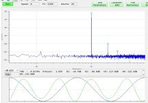
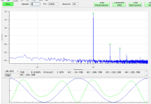
The distortion measurements are consistent with what Papa showed in the BAF 2023 video presentation.

The damping factor measured at around 26.

How does it sound? Amazing for such a simple amplifier with A/B listening against more powerful and lower distortion amplifiers. Plenty of power for my 88dB sensitivity speakers in rather large room.

Hats of to Papa, the circuit magician.

1702255520274.png


1702255341504.png


1702255230175.png
 
  • Like
Reactions: 9 users
Member
Joined 2010
I didn't mention the power supplies. The left channel, shown in the image of the provious post, is powered by 2 x Mean Well IRM-90-24ST power modules, with an simple RC output filter. The right channeel is powered from the "standard" 300VA +/-24 volt linear supply.

What is interesting is the noise floor with the Mean Well switching is 10dB lower that with the linear supply but both are good. There is no discernable noise with my ear to the speakers.

This suggests that the "cheapest" option for powering 2 channels of the F5m might be to use two higher output wattage, 24V switching supplies, such as the Mean Well LRS-150F-24 rather than the "standard" linear supply.

Shown below are the left and right channel distortion spectra at 1kHz, 1W, 8R load.
 

Attachments

  • F5mLCH-4V-8R-spectrum-20231210.jpg
    F5mLCH-4V-8R-spectrum-20231210.jpg
    83 KB · Views: 342
  • 1702256928363.png
    1702256928363.png
    66.9 KB · Views: 343
  • Like
Reactions: 3 users

6L6

Moderator
Joined 2010
Paid Member
This suggests that the "cheapest" option for powering 2 channels of the F5m might be to use two higher output wattage, 24V switching supplies, such as the Mean Well LRS-150F-24 rather than the "standard" linear supply.

It's not just less expensive, it seems to have some actual advantages, and as it turns out we've got a team (well, Mark, Patrick and myself...) working on a filtered solution for the LRS-150-24 and do exactly that!

:)
 
  • Like
Reactions: 16 users
Member
Joined 2010
With the simple RC filter I used, I couldn't see any problems with IRM-90-24ST noise. I did see a low level spike in the spectrum at around 48kHz due to fluorescent lights.

The big problems for reducing costs are the heatsinks and chassis. And eventually figuring out how to deal with the lack of p-channel jfets.
 
  • Like
Reactions: 1 user
The one and only
Joined 2001
Paid Member
Kit is due in the store shortly. Essentials kit includes power supply pcb. and C-H-E-A-P.

:snail:
 
  • Like
  • Thank You
Reactions: 27 users
Member
Joined 2004
Regarding the F5M, two questions come to mind:
1. What grade (Gr, B or V) JFET is required?
2. Why no gate stopper resistors?
 
Official Court Jester
Joined 2003
Paid Member
Pa is sort of cheating

:rofl:

seeing price difference in few 0207 resistors and few TO92 bjts and few small NTCs....

point is - he is going to organize this one for cheap in Store
 
  • Thank You
  • Like
Reactions: 1 users
Member
Joined 2020
I didn't mention the power supplies. The left channel, shown in the image of the provious post, is powered by 2 x Mean Well IRM-90-24ST power modules, with an simple RC output filter. The right channeel is powered from the "standard" 300VA +/-24 volt linear supply.

What is interesting is the noise floor with the Mean Well switching is 10dB lower that with the linear supply but both are good. There is no discernable noise with my ear to the speakers.

This suggests that the "cheapest" option for powering 2 channels of the F5m might be to use two higher output wattage, 24V switching supplies, such as the Mean Well LRS-150F-24 rather than the "standard" linear supply.

Shown below are the left and right channel distortion spectra at 1kHz, 1W, 8R load.

Have you seen any low frequency aliasing noise due to using two of the same switching supplies?

P.S. It actually wouldn't be LF (except relative to switching frequency), of course, and would "walk around" and allude measurement.
 
Last edited:
Member
Joined 2010
Have you seen any low frequency aliasing noise due to using two of the same switching supplies?

P.S. It actually wouldn't be LF (except relative to switching frequency), of course, and would "walk around" and allude measurement.
Maybe. When making distortion spectrum measurements I would occasionally see weird behavior that eventually went away. I should see if I can repeat that behavior and see if it only appears on the channel with the SMPS and not the channel with the linear supply.
 
  • Like
Reactions: 1 user
Member
Joined 2020
I can imagine that both fsw are so far down in level by the time they are in the audio circuit, that any aliasing would just be too low. But it's been a concern. It would be nice if you could sync different supplies, but I've never seem any of this type that have that feature.
 
Member
Joined 2004
Zen

Sorry for the time delay, other side of the planet in bed asleep. I thought B version would do and was curious about the 22k resistor's higher than usual value. Currently battening down for Cyclone Jasper, thank goodness has downgraded to a Category One, Yasi was the worst in 2011 at Cat 5. Part of the fun living in the tropics!
 
Top