Small mistake, I just realized that the internal resistance of the capacitors affects my output voltage, and considering the internal temperature of the enclosure, it will be around 3 ohms. My output voltage will be reduced to 23V.
I will go back to conducting some tests.
I will go back to conducting some tests.
Attachments
I just returned my order to them as the OPA604s did not look right. Back to searching for some genuine ones.OPA604 partsconnexion has them
I just returned my order to them as the OPA604s did not look right. Back to searching for some genuine ones.
 really? I admit idk how to tell and assumed they are a reliable source. I will pop mine out and test to see - if they are not real then they are probably killed by the +-24V rail by now?
Thank you, Jeff, for the LTspice file. I tried to tame the beast, but it's not that simple.Yeah, even 24.5 is probably too tight. You'd need to simulate the PSU is LTSpice (or equivalent) to see what the drop-out voltage of the series regulator is.
(I've attached the LTSPice file of the PSU I used if you want to modify it.)
Not to mention the lack of time. I went back to using PSUD and recreated your schematic (attached). I obtained an output of 23.7V RMS and a maximum of 25.2V with a 40-ohm load.
With a 1-ohm resistor in my CRCRC configuration, I achieved 23.6V RMS and 25V maximum, still with a 40-ohm load. My cutoff will be at 25Hz.
I can easily use a 0.82-ohm resistor to have a cutoff at 30Hz and obtain values identical to yours without modifying the transformer.
I have some 0.56-ohm 3W Panasonic resistors in stock, which would give me an approximate cutoff of 40Hz. The peak current on the first capacitor stage will be 2A, and I have a 20% margin, so I think it will be sufficient.
Have a great day!
Jérôme
Attachments


Hello,
I completely made a mistake with my capacitance values... I went back and here are the results:
- With CRCRC, I get 31.632V with a load of 600mA and 0.47 ohms, and 31.790V with 2.2 ohms on the CRC circuit.
So, I will stick with these values. However, I am switching to a 6800uF 80V capacitor for the first stage, which will provide enough margin with a current of 5.27A.
@JeffYoung : Should I recalculate the regulation section with a 0.15V difference? If yes, which resistor should I adjust? (R83-R87?)
Have a great day!
Jérôme
Attachments

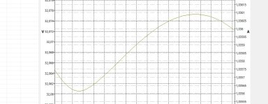
Set your reporting delay in PSUD2 to 1/2 a second. The "Diff" column for "V(R3)" will then tell you the height of the residual noise on the output. Do the same for the CRC version.
I suspect you haven't made a lot of difference with your CRCRC. If the residual noise isn't lower then all you've done is add complexity.
Raising the R in your CRCRC would make a difference, but at the loss of more voltage. Do you already have the transformer, or can you get one with a slightly higher output voltage? Then you could use 1R1 in your CRCRC which would have a much larger effect on the output.
Even if you already have a transformer, you might be able to get away with it. The commercial version of the HPA1 is designed to maintain regulation with something like a 10% sag in the mains voltage (I can't remember the exact figure). That can happen in rural environments, or near heavy industry (or a hospital -- ask me how I know). But if your mains voltage is very consistent, then you might not need as much headroom.
In CRCRC with 0.47 ohms, I have a voltage variation of 0.04V compared to 0.052V with 2.2 ohms on the CRC circuit. The gain is indeed low.
At 1.1 ohms, I obtain a voltage variation of 0.014V.
At 2.2 ohms, I get 0.003V.
Using the same diode bridge in both circuits will make it more scientific. I can easily switch to 1.1 ohm resistors with a voltage drop of 0.2V compared to the CRC circuit. My power supply is very stable, so I will order some 1.1 ohm resistors to ensure the voltage drop.
I still have some 2.2 ohm resistors from a previous build, so I will test them first.
The transformer (TOROIDY TTSA0120 2x25V) has already been ordered.
Attachments


Is it possible to use the PSU (for another project) for +-12V?So here's my clone of the HPA-1.
Is it enough to change the zener diodes D14, D18 to 12V, or would further adjustments be necessary?
I have been following this thread for a few months now, and finally going to build one for myself. In fact, 2 of my friends are going to build too, so we're going to build 3 of these
First, I would like to thank @JeffYoung for his amazing work! In fact we ordered PCBs based his his gerber files.
I have a few questions, since my build (despite using Jeff's PCB) is going to be a little different...
Main difference is: I am going to use a simple toggle-switch to select between SRC1 and SRC2. Also, simple toggle switch for PreAmp ON/OFF.
That means the entire control system is much simplified!
Now the actual questions:
1. Will I still need a 12V rail? or is that 12V rail only used for the control buttons / LEDs mechanism? Can I just use a transformer with 2 x 25V secondaries, and forget about 12V rail?
2. Original HPA-1 has 2 inputs and 1 pre-amp output. @JeffYoung What are the 2 outputs in your PCB design? Did you design 2 preamp outputs? Selecting preamp as output (in front panel) turns both ON or OFF at the same time? I only need 1 preamp output, so should I just wire the RCAs to OUT1 and forget about OUT2?

3. For implementing 2 inputs selected by toggle switch - I can think of 2 possible solutions:
3a. Feed both inputs to the toggle switch, and wire the switch output to say SRC1 on the PCB. Then, I need to mod the input select portion of the PCB to "always select SRC1". (I will need guidance for that piece)

3b. Wire 1 RCA pair to SRC1, and the 2nd RCA pair to SRC2. Need to wire the toggle switch to the right pads in the control section of the PCB so flipping the switch will choose SRC1 or SRC2. Again, I will need guidance on how to do that.

4. Similarly, how do I wire a toggle switch to turn ON/OFF the preamp output (instead of using the buttons and relays etc.)?

Thanks in advance for ANY help!!
I am eager to start working on it - I have all the parts in-hand other than the transformer. After figuring out answer to question #1 above - I can order a transformer with or without 12V secondary
Zachi.
First, I would like to thank @JeffYoung for his amazing work! In fact we ordered PCBs based his his gerber files.
I have a few questions, since my build (despite using Jeff's PCB) is going to be a little different...
Main difference is: I am going to use a simple toggle-switch to select between SRC1 and SRC2. Also, simple toggle switch for PreAmp ON/OFF.
That means the entire control system is much simplified!
Now the actual questions:
1. Will I still need a 12V rail? or is that 12V rail only used for the control buttons / LEDs mechanism? Can I just use a transformer with 2 x 25V secondaries, and forget about 12V rail?
2. Original HPA-1 has 2 inputs and 1 pre-amp output. @JeffYoung What are the 2 outputs in your PCB design? Did you design 2 preamp outputs? Selecting preamp as output (in front panel) turns both ON or OFF at the same time? I only need 1 preamp output, so should I just wire the RCAs to OUT1 and forget about OUT2?
3. For implementing 2 inputs selected by toggle switch - I can think of 2 possible solutions:
3a. Feed both inputs to the toggle switch, and wire the switch output to say SRC1 on the PCB. Then, I need to mod the input select portion of the PCB to "always select SRC1". (I will need guidance for that piece)
3b. Wire 1 RCA pair to SRC1, and the 2nd RCA pair to SRC2. Need to wire the toggle switch to the right pads in the control section of the PCB so flipping the switch will choose SRC1 or SRC2. Again, I will need guidance on how to do that.
4. Similarly, how do I wire a toggle switch to turn ON/OFF the preamp output (instead of using the buttons and relays etc.)?
Thanks in advance for ANY help!!
I am eager to start working on it - I have all the parts in-hand other than the transformer. After figuring out answer to question #1 above - I can order a transformer with or without 12V secondary
Zachi.
Yes, the 12V is only for the front panel and the relays that the front panel controls. One caveat to leaving it out: the front panel logic doesn't connect either output (cans or pre-out) for something like 10 seconds. I don't know what kind of turn-on thump the amp has (if any) without that provision.
The two outputs are identical. (I run a mono-block power amp from each of R & L of one of them, and a line-level subwoofer from the other pair.). If you don't need that you can just hook a single pre-out to one of them.
For switching inputs ignore the front panel stuff. Just patch your A/B switch in where the relays are (K1 and K2).
Thanks Jeff.Yes, the 12V is only for the front panel and the relays that the front panel controls. One caveat to leaving it out: the front panel logic doesn't connect either output (cans or pre-out) for something like 10 seconds. I don't know what kind of turn-on thump the amp has (if any) without that provision.
Anyone here used Jeff's PCB bypassing the front panel controls? I would love to hear from you what turn-on thump (if any) I should expect?
As I suspected. Thanks for confirming that.The two outputs are identical. (I run a mono-block power amp from each of R & L of one of them, and a line-level subwoofer from the other pair.). If you don't need that you can just hook a single pre-out to one of them.
Jeff, I assume you never designed a version without the front panel controls?For switching inputs ignore the front panel stuff. Just patch your A/B switch in where the relays are (K1 and K2).
- Home
- Amplifiers
- Pass Labs
- Pass HPA-1, what do we know?