This is my first time wiring balanced signal connectors. Am I correct in assuming that; A) For safety, connectors dispensing power (DC) should be female to avoid the possibility of human contact with the live pins; B) With balanced signal connectors, the male pins should always point in the direction of the signal flow. (Presumably to prevent some form of interference.) I've seen inconsistencies with this protocol.
Just found the tiny bit caps. Unlike the tiny Jfets, I cant tell if there is a up or down side to them? Even under magnification, I can see no difference
as far as top or bottom.
In the short video included in the build guide, there was no mention either so I assume I am good to go. Where does 6l6 get that extra thin tape
From anyway? LOL.
Russellc
as far as top or bottom.
In the short video included in the build guide, there was no mention either so I assume I am good to go. Where does 6l6 get that extra thin tape
From anyway? LOL.
Russellc
@DualTriode
Yes the OPA stage must maintain enough gain, if only to perform the RIAA function.
If one wanted less than 50dB gain, I would suggest reducing the gain in the first stage (jfet) together with increasing the overall feedback (lowering R22). Perhaps an approach for the former is replacing R1 by, say, three 220R in series and connecting one of the taps to the coupling cap? Lowering the overall gain by 6 dB would give ~20dB overload margin to a 5mV MM cartridge. (Apologies if this is not the appropriate thread for mods.)
Want more headroom? Increase the rails to what the OPA will tolerate (e.g. from 15 to 18V). Beyond this I think it is easier to go all discrete (e.g. Paradise) or turn to tubes. IMO.
Yes you are good to go 👍.Just found the tiny bit caps. Unlike the tiny Jfets, I cant tell if there is a up or down side to them? Even under magnification, I can see no difference
as far as top or bottom.
In the short video included in the build guide, there was no mention either so I assume I am good to go. Where does 6l6 get that extra thin tape
From anyway? LOL.
Russellc
Thanks, Ifigured so and went ahead. If I missed something I figured probability should give me half right, so only 4
would possibly be "upside down" or whatever. Thanks for closing the book on that question! I looked at them under magnification and no difference could I detect. Thanks again.
Russellc
would possibly be "upside down" or whatever. Thanks for closing the book on that question! I looked at them under magnification and no difference could I detect. Thanks again.
Russellc

Hello All!
I finished the build and have a couple of problems.
1) When the power switch is turned on, there is a loud pop...that sounds like someone is dropping the needle on the record. This also happens when switched off.
2) Once the unit is powered up, it is silent until I play a record. The cartridge hits the vinyl, then a high-pitched wine that sounds like an old radio in between stations is present. The unit seems to function well otherwise.
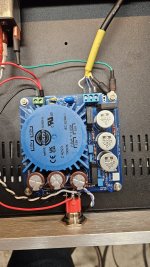
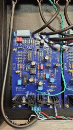
I am attaching photos and am hoping someone will help me troubleshoot. I have no clue where to begin.
I will admit that I made a mistake building the power supply and managed to install the caps backwards-something I will never do again. I replaced all three on that side for good measure. Now, I think that I may have damaged something else.
Any words of wisdom are appreciated...
I finished the build and have a couple of problems.
1) When the power switch is turned on, there is a loud pop...that sounds like someone is dropping the needle on the record. This also happens when switched off.
2) Once the unit is powered up, it is silent until I play a record. The cartridge hits the vinyl, then a high-pitched wine that sounds like an old radio in between stations is present. The unit seems to function well otherwise.
I am attaching photos and am hoping someone will help me troubleshoot. I have no clue where to begin.
I will admit that I made a mistake building the power supply and managed to install the caps backwards-something I will never do again. I replaced all three on that side for good measure. Now, I think that I may have damaged something else.
Any words of wisdom are appreciated...
Attachments

Well yes i was, but will not in the future. I just did not know if that was to be expected.
I made some progress in addressing the whining issue. It seems that when I connect the turntable ground to the ground pin of the XLR, the whining stops. Although I installed the XLR drivers initially with the intention of using them, I'm not currently utilizing them. I was using an audio probe to locate the source of the noise. What's odd is that connecting the turntable ground to the grounding post doesn't make any difference. I have everything grounded correctly and double checked..??
I made some progress in addressing the whining issue. It seems that when I connect the turntable ground to the ground pin of the XLR, the whining stops. Although I installed the XLR drivers initially with the intention of using them, I'm not currently utilizing them. I was using an audio probe to locate the source of the noise. What's odd is that connecting the turntable ground to the grounding post doesn't make any difference. I have everything grounded correctly and double checked..??
Reducing Gain
As has been pointed out, reducing R22 to lower the input stage gain can adversely affect distortion performance by overloading the output stage of U1a. At some point, the open-loop output impedance of the op-amp becomes a limiting factor. 220 Ω already seems to be close to the lower limit of impedance that can be driven with low distortion. Raising the value of R8 would be a better approach, and can be compensated at least partially by lowering the value of R4-R7. Provided R8 isn't increased too much, there should be minimal effect on the input-referred noise performance. 12 or 15 Ω would be reasonable values to try, for a modest gain reduction of 3.3~3.5 dB. If your input stage is running 2SK170 instead of the standard 2SK209, increasing R8 would also help reign in the tendency toward high quiescent current & Q5 saturation as a side benefit.
You can reduce the gain of the 2nd stage by increasing R18 and reducing R15 by the amount you've increased R18. Adjust C8 to maintain the same time constant with R18.
e.g. to reduce gain by 6 dB: R18 = 440 Ω, R15 = 3.10 kΩ, drop C8 from 220 µF to 110 µF (100 µF nearest practical value)
C5 shouldn't need much if any adjustment unless you're making larger changes to R15.
I posted a pair of LTspice decks here which you can use to simulate component value changes to the front end & EQ stages. The latter is particularly useful for fine tuning your EQ component values based on the actual measured part values you have on hand.
...on the subject of tweaking EQ components, I noticed that R13 benefits from a correction to 760 Ω, since the presence of R28 has the effect of slightly lowering the 75 µs time constant. If you're matching caps by hand, you could alternatively try to select a higher value for C3 - I calculated 101.5nF as an optimal value. I was able to find a matching pair caps for the C3 position at 100.9 nF out of the stock that I had, which was not enough on its own to fully correct the time constant.
Note that raising R28 helps a bit, but also lowers the LF cutoff frequency a bit - whether that concerns you or not is a matter of preference. I would personally prefer not to let the LF cutoff drift too low as I run a pair of subwoofers and therefore do want to keep the rumble frequencies under control.
After some more fiddling, I found that a slight reduction of R15 could mostly compensate for the remaining error in the R13 / C3 time constant. I soldered a high-value resistor in parallel with R15 on my boards to implement this adjustment.
Final assembly of my P3 boards should happen soon, and then I'll try to get some measurements to confirm the real-world performance matches simulation.
Here's how the EQ looks with default circuit values (exact), and then with R13 = 762 Ω and R15 = 3.313 kΩ. It's a pretty tiny change, but if you're fussing with hand-matched component values then perhaps worth the extra little effort.
Attachments


Last edited:
- Home
- Amplifiers
- Pass Labs
- Pearl 3 Burning Amp 2023