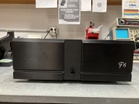
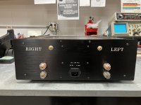
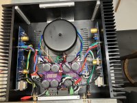
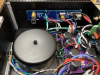
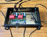
My F6. I'm using the DIYStore F6 PCB's along with R. Thatcher P/S, and rectifiers with snubber PCB's. Mounted on the back panel is Mark Johnson's soft start with low voltage on/off (H9KPXG) with the BIG inrush current limiter. Antek AS-4218 torroid transformer with steel cover.
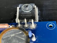
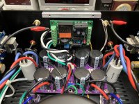
The output devices are SemiSouth SJEP120R063 SiC JFET's, this is an all JFET devices amplifier.
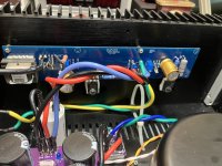
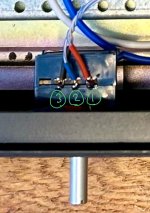
I swapped the zener diodes for blue LED's ( I had to ignore the zener symbol on the PCB for the blue LED's) and set bias to 150mV on Q1 with Q2 = 148.6mV using 0.1 ohm source resistors. The input resistors are Vishay Z-Foil naked resistors I had in stock and Audio Note gold capacitors. Nelson stipulated a 100 ohm 5W resistor for the feedback resistor, so I used MOX 100 ohm 5w.
The left channel board is stable as a rock for bias and offset, the right channel has the bias stable, however, the offset varies from 1.2mV to 44mV in 5 minutes. I keep adjusting the offset back to close to zero, however it continues to vary. I wonder if I need to increase the gate resistors to a value greater than the 47 ohm specified?
I need to clean some rosin dust off the boards and hook up the front panel LED after I find the brightness I prefer.
I'll power it up for a few hours and see what happens to the offset on the right channel.
The output devices are SemiSouth SJEP120R063 SiC JFET's, this is an all JFET devices amplifier.
I swapped the zener diodes for blue LED's ( I had to ignore the zener symbol on the PCB for the blue LED's) and set bias to 150mV on Q1 with Q2 = 148.6mV using 0.1 ohm source resistors. The input resistors are Vishay Z-Foil naked resistors I had in stock and Audio Note gold capacitors. Nelson stipulated a 100 ohm 5W resistor for the feedback resistor, so I used MOX 100 ohm 5w.
The left channel board is stable as a rock for bias and offset, the right channel has the bias stable, however, the offset varies from 1.2mV to 44mV in 5 minutes. I keep adjusting the offset back to close to zero, however it continues to vary. I wonder if I need to increase the gate resistors to a value greater than the 47 ohm specified?
I need to clean some rosin dust off the boards and hook up the front panel LED after I find the brightness I prefer.
I'll power it up for a few hours and see what happens to the offset on the right channel.


")
