I have been experimenting with a circuit modification that rweduces the transconductance of either of the output stage FETs in order to "tune" the gm balance. The first two image show the output stage with an added RX potentiometer and capacitor between the NFET gate and source.


I chose a pair of FQA28N15 and FQA36P15 FETs that had transconductances of 4.59S and 3.90S, giving a gm ratio of 1.18, which is higher than what I distributed as "matches" to the Holy Grail OS builders.
I made spectral measurements without the RX pot in circuit (column 1 of image 1) and with the RX pot adjusted for equal AC voltages across sense resistors R1 and R2 when for a 1 Watt (column 2 of image 1), 60Hz output into 8 Ohms.
I also chose a very rare pair of FQA28N15 and FQA36P15 FETs that had nearly identical gm to start with and made spectral measurements (column 3 of image 1).
The rows of image 2 are wattage sweeps for 8 Ohms, wattage sweeps for 4 Ohms, and frequency sweeps at 1 Watt into 8 Ohms.
With the RX adjustment, the 2nd harmonic of the unbalanced FQA FETs is somewhat reduced by around 6dB.

I performed the same spectral measurements and RX pot adjustment for the pair of IRFP140 and Harris IRFP9140 FETs, shown in image 2 compared to the well matched FQA FETs in column 3.
With the RX adjustment, the 2nd harmonic of the IRFP FETs is reduced by 20dB at 1 Watt and interestingly, the 3rd harmonic is also significantly reduced at high wattages.
Conclusion: The RX pot adjustment made a significant reduction of all harmonics for the IRFP FETs, but not much for the FQA FETs that were already reasonably well matched.

I made spectral measurements without the RX pot in circuit (column 1 of image 1) and with the RX pot adjusted for equal AC voltages across sense resistors R1 and R2 when for a 1 Watt (column 2 of image 1), 60Hz output into 8 Ohms.
I also chose a very rare pair of FQA28N15 and FQA36P15 FETs that had nearly identical gm to start with and made spectral measurements (column 3 of image 1).
The rows of image 2 are wattage sweeps for 8 Ohms, wattage sweeps for 4 Ohms, and frequency sweeps at 1 Watt into 8 Ohms.
With the RX adjustment, the 2nd harmonic of the unbalanced FQA FETs is somewhat reduced by around 6dB.
I performed the same spectral measurements and RX pot adjustment for the pair of IRFP140 and Harris IRFP9140 FETs, shown in image 2 compared to the well matched FQA FETs in column 3.
With the RX adjustment, the 2nd harmonic of the IRFP FETs is reduced by 20dB at 1 Watt and interestingly, the 3rd harmonic is also significantly reduced at high wattages.
Conclusion: The RX pot adjustment made a significant reduction of all harmonics for the IRFP FETs, but not much for the FQA FETs that were already reasonably well matched.

But you need to know which FET has a higher transconductance first, and place the trimpot there.
And you need a distortion analyser.
Also, in doing so, you increase effective output impedance, because essentially, you are reducing the effective transconductance of the FET with the trimpot to enable better harmonic cancellation.
No free lunch.
Patrick
And you need a distortion analyser.
Also, in doing so, you increase effective output impedance, because essentially, you are reducing the effective transconductance of the FET with the trimpot to enable better harmonic cancellation.
No free lunch.
Patrick
No distortion analyzer is needed. The relative transconductances are measured by the AC voltages across the sense resistors when the amplifier is driven at around 1 Watt , 60Hz into an 8 Ohm load. The FET whose drain sense resistor has the larger AC voltages across it has the larger transconductance.
Yes, obviously decreasing the gm of one of the FETs also decreases the combined gm of the output stage, increasing the effective output impedance.
Yes, obviously decreasing the gm of one of the FETs also decreases the combined gm of the output stage, increasing the effective output impedance.
No distortion analyzer is needed. The relative transconductances are measured by the AC voltages across the .....
That would work if the 2nd and higher harmonic terms have the same proportional constant to the transconductance between the two devices,
I.e. you can achieve harmonic cancellation by balancing current sharing between NMOS & PMOS.
Cheers,
Patrick
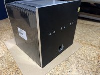
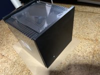
Today the chassis’s parts arrived 😎
Slowly building up, part by part. Trying to avoid glitches, one already happened by lack of cad: the outermost connectors are too close to the HS, file away!
(Still waiting for the trannies.)
Slowly building up, part by part. Trying to avoid glitches, one already happened by lack of cad: the outermost connectors are too close to the HS, file away!
(Still waiting for the trannies.)
Attachments
By keeping the test signal low (1W into 8R), the harmonics are an insignificant part of voltages being measured.
So in your experiments, the minimum distortion point happens to correspond to equal current sharing between NMOS and PMOS ?
And that applies to all FET pairings, correct ?
Interesting,
Patrick
With my limited tests I would not claim that the minimum distortion point happens to correspond to equal current sharing between NMOS and PMOS.
But there is something unexplained that puzzles me. The 2nd harmonic can be adjusted in many ways. Why is the growth of the 3rd harmonic vs. watts greatly reduced when the gms are balanced?
But there is something unexplained that puzzles me. The 2nd harmonic can be adjusted in many ways. Why is the growth of the 3rd harmonic vs. watts greatly reduced when the gms are balanced?
Good afternoon!
I’ve a question about input-connection:
@lhquam , you are pulling 3 wires from the input-rca‘s, one is in+, one is in-, the third goes to gnd… would I make it less perfect if I went with a „jumper“ from in- to gnd instead of using a separate wire from the connector to gnd? And could you please explain why this is done this way? I believe I have come across this configuration in the BA18 Wayne‘s Line Stage, right?
The primary reason that I use 3-wires to the RCA connector is that it can be difficult to insert 2 wires, one to the RCA connector and one to In- into the same Gnd (or GndR) position of the small 4-pin connector block.
However, you could solder the jumper wire to the RCAGnd wire so that only one wire needs to be inserted into the connector block.
However, you could solder the jumper wire to the RCAGnd wire so that only one wire needs to be inserted into the connector block.
I plan to redo the measurements with no global feedback, I will also look at the minimum distortion vs. gm balance question. When you say "minimising distortion" are you referring to THD, H2, or something else?I assume you have means to measure distortion ?
So you can adjust the trimpot by minimising distortion.
And then you can go back to check whether current sharing is equal.
Not ?
Patrick
I have a technical question.
I've seen you try multiple pairings. FQA28N15 and FQA36P15. IRFP140 and IRFP9140 Harris and others. IRPF240 and IRFP9240. IXTN140N30P and IXTN40P50P
what about FQA28N15 and IRFP9140 (Harris and other), IXTN40P50P, IRFP9240
So my question is is there anything truly preventing testing N Channel VS P Channel MOSFETs?
You are busy and the variations could be endless. Cannot spend every day testing variations, unless that is your kind of fun!
is there a large transconductance difference within these parts that prevents them from being a good match?
I know that after following this thread for a while, several possible variations can be tried. The only issue is what parts are available and at a decent price. I think FQA28N15 is still out there and can be purchased for a decent price. IXTN140N30P and IXTN40P50P are also out there, maybe a bit more expensive but still available. heck, the store still has the Harris IRFP140 and IRFP9140.
Sorry for the long post, it is just been something that I have been curious about for a while.
Edit: A little timid way of asking about the P-Channel MOSFET being a bit more hard to source/expensive. Again my curiosity, and not trying to start any controversy.
Best,
Jose
Last edited:
All good questions. When initially testing NFET/PFET pairs for this project I got lucky early on with the FQA28N15/FQA36P15 pair being so good that I stopped looking further. With the use of the gm adjustment shown in post #541 is should be possible use other FET combinations and achieve similar or better performance. In fact the OnSemi IRFP140/Harris IRF9140 combination look very good.
The problem that you point to is the availability of suitable power PFETs, and to a lesser extent NFETs.
There is still a source for the Harris IRF9140 that I found: componentonline.com. The FQA36P15 is still available from Polida on EBay.com. I have Harris IRFP9240 FETs on order from Polida to test. My tests with the ONSemi IRFP9240 were not encouraging.
I encourage people to explore using IXYS FETs. I have only tried the IXYS IXTQ36N30P and IXTQ36P15P which didn't perform as well as others.
- Home
- Amplifiers
- Pass Labs
- The Holy Grail Follower Output Stage