most cumbersome amps I dealt with in my workshop were:
considering pain I had just to put them on the bench, then to rotate while working on, in one moment I was thinking of implementing some sort of ceiling crane, to have for future

- some old 5channel PA Dynacord (2*2KW Donuts and zillion of strongest Hitachi TO3 mosfets)
- Unison Research ABSOLUTE 845 (that one is so bad in some areas that I imagine them paying ppl just to take it)
- Babelfish Aleph JX monoblocks
considering pain I had just to put them on the bench, then to rotate while working on, in one moment I was thinking of implementing some sort of ceiling crane, to have for future

Most class A designs are heavy by default due to their inefficiency. My example of Ben's original design for this amp weighs around 36kg. Its a solid workout for me to move it from workshop bench to listening room. I used a Modushop 4U/300 case partitioned horizontally using 3mm plate aluminum. Meanwell LRS150 SMPS's, Hammond 159ZJ chokes (for CLC), Hammond 195T5 chokes and AC wiring on lower level. PCB's, soft start module, bias supply transformer, filter and output caps on top level. Using a matched pair of THF51S instead of 2SK180. Vds 35V, Iq 2.5A. Sound is sublime at this operating point. I've recently added a pair of Noctua 200mm fans to both heatsinks. They run quite slowly on about 9V which provides sufficient forced air to keep the entire chassis and heatsinks close to ambient temperature, even in hot Australian summer, and are virtually silent. Modifications in progress are change to Ben's new PCB's with negative Vcc. A few photos follow.Yes it will be heavy but I’m trying to make it as compact as possible. AND still keep it silent & cool
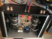
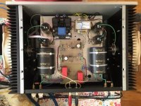
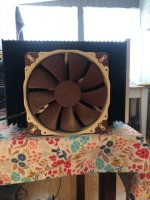
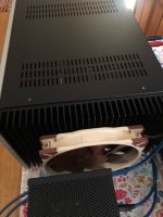
The SMPSs saved you a bit of weight. Imagine the weight with two large power transformers.
These SITs are very versatile. Great sound can be had with many different configurations.
You mentioned the original design, so it is common source with voltage gain? My second design and the latest Vcc- design are common drain, no voltage gain, and lower distortion. It will sound a bit different and in my opinion better.
Although a linear PS may be better, I wasn't keen on the extra weight and expense of a pair of 200-300VA transformers. It would have been unmoveable by one person. With a CLC on the SMPS output (10mF-159ZJ-5mF), I measured ripple on Vcc at ~ 0.2mV and the amp is totally silent on speakers and headphones. There may well be high frequency noise present at low levels, but it doesn't seem to get in the way of the music.
I've tried a different operating point (Vds=38V, Iq=3A). Apart from a bit more power and heat, it didn't sound much different.
I should have clarified "original design" by adding original common drain version, as described in post #109 (your second design).
I'm looking forward to trying the Vcc- version in due course. Apart from replacement of existing amp and bias supply stripboards with the new PCB's, it won't require a lot of modification to the existing physical layout.
I found a very nice power supply: Meanwell-ENP Desktop. It looks like a very solid alternative."a pair of 200-300VA transformers. It would have been unmoveable by one person. "
You don't have to be a body builder. Not even a cash machine.
But - it will want another operating point. up to 30V or from 45 V. But some users claim to have changed a feedback resistor to get the voltage they want. . . Well, it is DIY, isn't it? And the DIY heaven is stacked with failed adoptions (at least over here)
Attachments
Ben I have built your amp boards. I am getting no voltages from the choke and sit test positions even when the bias resistor is adjusted.I have left the input open and a 10 ohm resistor on the output.Any ideas on what I've done wrong, thanks Mick.
Did you test the build in stages? For instance did you test the main power supply and the bias power supply on their own before connecting them to the board?
Are you using a 2SK180? What Vds do you measure (VDC, red on drain, black on source)? What Vgs do you measure (VDC, red on gate, black on source)?
Post pictures of the overall setup showing all wiring and some of the power supplies and amplifier board.
Edit: Deleted sentence, I was confusing this amplifier with my Mu follower follower project.
What choke are you using? Hammond 193V? If so it has DC resistance of 1 Ohm. If it is a different choke, you need to know its DC resistance.
To measure the current, measure the voltage drop across the choke, There are two Test Points on the board, "TP V- Choke1" and "TP Choke2 SIT S". Measure the voltage with meter probes on those two points. Then use Ohm's Law, Current I = V/R .
Edit: deleted sentence, same reason
Edit: Please read my post #685: Post #685
Last edited:
triode_al
Meanwell ENP Desktop SMPS looks like an alternative to a PS built in to the amp chassis ie. an external PS. I'm using Meanwell LRS-150-36 (one per channel) which are small enough to fit inside the Modushop amp chassis. They are nominally 150W and 36V with adjustment from 32 to 39V, which is ideal for fine tuning this amp.
Ben
I have rebuilt the amp using your new design and PCB. With both main and bias PS's connected but without SIT in circuit, all appears OK. Voltages are roughly where they should be according to the schematic, bias voltage is adjustable and LED is on. When SIT is connected (with bias adjustment trimmer fully counter clockwise), the main PS (SMPS) goes into hiccup mode, which indicates a direct short circuit across its output. My interpretation of this is that there is zero resistance between source and drain of the SIT. Would this be correct? I have checked and rechecked all component values (including the SIT) and their placement on the PCB's as well as external wiring and connections. The strange thing is, I have been using this SMPS in your earlier design (+Vcc) for almost a year with same SIT (THF51S) and choke without any issues. I have also used it without problems in a MOSFET source follower design (Power Follower 2021 by Andrea Cuffoli), which uses -Vcc. That is, the SMPS works with both grounded negative and grounded positive designs. As noted in my previous post, I'm using a Hammond 195T5 choke which has a nominal DC resistance of 0.64 ohms (measures 0.61) which is quite a bit lower than the 193V. The only possible causes of this problem I can think of are differences between the 2SK180 vs THF51S, and 193V vs 195T5, and their interactions in this design. I have ordered a 193V to eliminate one variable, but I'm not entirely convinced the difference between them is the source of the problem. Any thoughts or comments would be very welcome.
Other things you can check:
1. With no SIT connected, power up and measure Vg at the trimmer min and max settings. Also measure Vs. All voltages relative to ground.
2. Check you SIT :

The 195T5 or THF-51S should not cause any major issues. If the circuit is operating as it should, the only problem that I can see is that if your SIT needs a very high Vgs to shut down. The circuit as is should be capable of a maximum Vgs of about -9.5V or so. That should take care of most Tokins.
1. With no SIT connected, power up and measure Vg at the trimmer min and max settings. Also measure Vs. All voltages relative to ground.
2. Check you SIT :
The 195T5 or THF-51S should not cause any major issues. If the circuit is operating as it should, the only problem that I can see is that if your SIT needs a very high Vgs to shut down. The circuit as is should be capable of a maximum Vgs of about -9.5V or so. That should take care of most Tokins.
Ben
Thanks for your reply and suggestions.
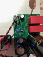
I think trimmer orientation is correct (see photo below).
Check of SIT with multimeter (Ohms range) confirmed results as above, so probably safe to assume it is OK.
Results of suggested voltage checks (Vcc = -37.5V):
Vg (maximum counter clockwise) = -39.13V
Vg (maximum clockwise) = -37.15V
Vs = -37.5V
Vgs SIT not connected: maximum counter clockwise = -1.63V (negative probe on source)
Vgs SIT not connected: maximum clockwise = +0.35V (negative probe on source)
Raw bias DC voltage (from rectifier) = 20.85V

There is a problem with the bias supply. Vg max should be about -46.5V.
Disconnect the V- power supply, no SIT installed, power up the bias supply, and check Vg. As mentioned previously, Vg max should be about -9.5V (without V- power supply).
Check resistor values in LM317 bias circuit, especially R1, R2 (240, 2k) and R7, R8 (5k,5k).
Disconnect the V- power supply, no SIT installed, power up the bias supply, and check Vg. As mentioned previously, Vg max should be about -9.5V (without V- power supply).
Check resistor values in LM317 bias circuit, especially R1, R2 (240, 2k) and R7, R8 (5k,5k).
Last edited:
- Home
- Amplifiers
- Pass Labs
- 25W Single Ended Hammond 193V Choke Loaded 2SK180 L'Amp