I am SMPS illiterate.
It is interesting that the SMPS powered DIY Sony Part 1 (P channel) has drain grounded and the DIY Sony Part 2 (N channel) has V+ to drain. So in both cases the SMPS Ground is at circuit ground. The SMPS was not reversed in the N channel version. Nelson knows what he is doing. I stay away from SMPS because I don't.
Maybe the SMPS needs modification before it can be reversed with V+ at Ground. Again, I am SMPS illiterate.
The bias voltage (at SIT gate) is negative because the floating bias voltage supply is in series with V-, with the bias voltage positive connected to V- and the bias supply negative connected to the SIT gate. So at maximum, relative to circuit ground, the voltage at SIT gate relative to ground should be about -11.7V when V- is not on. When V- is on, it should be about -46.5V relative to circuit ground.
When you measured -11.7V, was this at the SIT gate relative to circuit Ground with no V-? I do not understand what you measured when you said you measured -11.7V bias voltage referenced to bias supply ground.
So with the SMPS test, did you turn on the bias voltage, wait until you measured -11.7 voltage at the SIT gate relative to circuit ground, and then powered up the SMPS? Did you have a meter measuring V-? Did you have a meter across the choke to measure current? That information would be helpful for troubleshooting (Vg and V- relative to circuit ground, and Vdrop across choke readings as V- power is applied).
Do you have another power supply for testing? It does not have to be 36V. A 19V computer supply? Or a linear supply? It would be to test the circuit.
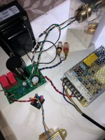
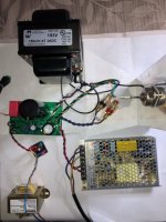
Post some clear pictures of the board and of your whole amplifier, showing all wiring.
Apologies for confusion with ground reference points. I should have measured with reference to TP GND. To clarify:
Vg max, trimmer full counterclockwise, without SIT in circuit, no V- = -11.7
Vg min, trimmer full clockwise, without SIT in circuit, no V- = 0.0
Vg max, trimmer full counterclockwise, without SIT in circuit, V- connected = -46.6
Vg min, trimmer full clockwise, without SIT in circuit, V- connected = -36.8
V- referenced to TP GND (SIT not connected) is -37.5V. Its not possible to measure V- and voltage drop across choke when SIT is connected as PS goes into protection mode.
Re other power supply, I have a laptop SMPS that can provide 19-24VDC and would probably be suitable. Also, a linear benchtop 30V 3A laboratory PS but I doubt it has short circuit protection.


Does your lab supply have variable voltage and also maximum current limiter. If it does, you can set the current limit to a low value such as 1A and start the voltage at zero and slowly increase. Place meters to measure Vgs, Vds, and V drop across choke. With the THF-51s, it is easy to connect directly to the THF-51S for Vds and Vgs.
First power up the bias supply and make sure that Vgs is at maximum. Then turn on the lab supply V- and slowly increase the voltage. Is there any current flow through the choke? Use Ohm's Law to determine current (I = V/R where R is the choke's DC resistance). Vgs should stay constant. If you can increase the lab supply V- with no current flow that is good. Continue increasing V- to about -20V. Next start adjusting the trimmer clockwise . Vgs should start dropping and at some point current should start flowing, and voltage should appear across the choke.
First power up the bias supply and make sure that Vgs is at maximum. Then turn on the lab supply V- and slowly increase the voltage. Is there any current flow through the choke? Use Ohm's Law to determine current (I = V/R where R is the choke's DC resistance). Vgs should stay constant. If you can increase the lab supply V- with no current flow that is good. Continue increasing V- to about -20V. Next start adjusting the trimmer clockwise . Vgs should start dropping and at some point current should start flowing, and voltage should appear across the choke.
The way it is currently connected to the Tokin Follower PCB is floating. That is, V+ isn't connected to safety ground.rolotube, how is the Meanwell SMPS connected? It needs to be floating.
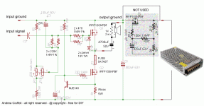
I've used this SMPS to provide V- (with V+ grounded) in Andrea Cuffoli's Power Follower design. He replaced the original linear regulated supply with Meanwell LRS150 claiming it was quieter (https://www.audiodesignguide.com/PowerFollower/index3.html)

For now try using your lab supply. If your lab supply does not have a current limiter, you can still use it. Wire a fuse in the DC line to the amplifier board. Also by starting the lab supply at zero Volt and slowly increasing the voltage you can stop if you see the current rising too fast. If the circuit is working properly, there should be no current flowing with the bias voltage set to maximum. Even if you do not have a fuse in the V-, starting at zero Volt and slowly increasing the voltage and observing the current through the choke should give you time to shut down the lab supply.
All is well - amp is running as it should with lab PS. Put a 1A fuse in V- line, just in case. Powered up bias, let it settle at -11.7V, then slowly increased voltage to 24V. Trimmer was then wound clockwise to get current flowing through SIT. Currently running happily at 1A. Vds = 22.4V. Vg = -25.6V. SIT (using 2SK182ES for this test) is warm after 15 minutes.For now try using your lab supply. If your lab supply does not have a current limiter, you can still use it. Wire a fuse in the DC line to the amplifier board. Also by starting the lab supply at zero Volt and slowly increasing the voltage you can stop if you see the current rising too fast. If the circuit is working properly, there should be no current flowing with the bias voltage set to maximum.
So problem is not with PCB, its the SMPS. Despite working with grounded V+ in the Power Follower, for whatever reason it won't work in this configuration with the Tokin Follower.
Many thanks again to all for comments, suggestions and assistance.
That is good news, at least for the amplifier board and circuit.
The only thing that I can think of regarding the SMPS is that it is in series with the bias supply. That way I could use a low voltage bias supply. Without the V- supply in series with the bias supply, the bias supply voltage would need to be the sum of V- and Vgs, so in the neighbourhood of -50V maximum to be on the safe side.
I found a Meanwell manual that does mention supplies in series. See page 84 where it mentions that series supplies should have a diode connected to the SMPS output. So try attaching an 1N4002 to the SMPS output (cathode to V+).
Attachments
I read the article. Sadly, it didn't work.So try attaching an 1N4002 to the SMPS output (cathode to V+).
No joy with soft start.
Forget the two SMPS suggestion. I think it would require a major redesign of the PCB and probably introduce undesirable noise into the bias and V- supplies. Possibly more trouble than its worth. Now I know PCB's are OK, I'll redesign the amp using a linear PS. It'll likely require monoblocks as two PS transformers, PS chokes and amp chokes (195T5) add up to a substantial weight. It might be dooable on one chassis but it would be very difficult to move.
Forget the two SMPS suggestion. I think it would require a major redesign of the PCB and probably introduce undesirable noise into the bias and V- supplies. Possibly more trouble than its worth. Now I know PCB's are OK, I'll redesign the amp using a linear PS. It'll likely require monoblocks as two PS transformers, PS chokes and amp chokes (195T5) add up to a substantial weight. It might be dooable on one chassis but it would be very difficult to move.
- Home
- Amplifiers
- Pass Labs
- 25W Single Ended Hammond 193V Choke Loaded 2SK180 L'Amp
