I am still wondering why the Meanwell does not work. If the bias voltage is high enough to shut off the SIT so no current will flow, why does the Meanwell shut down?
When you have the SIT installed, bias voltage on and at maximum, what instantaneous meter readings do you get when you turn on the Meanwell? Does the Vgs stay constant? Does Vds jump to a voltage and then instantly go back to zero? Does the voltage drop across the choke jump up and then go back to zero?
In your V+ follower amp, what did you do for bias voltage supply?
Can you connect the Meanwell back to your V+ follower amplifier to confirm that it is still working properly?
If you use an independent high voltage SMPS for bias voltage, the pcb can still be used. The voltage regulator and its voltage setting resistors and safety diodes would be deleted. One trace would be cut. And the bias supply V+ (ground) would be connected to the circuit ground. So both SMPS V+ would be connected to circuit ground.
But the question is still why the SMPS is not working right now.
Possibly the charging current into the output capacitor on start-up is high enough to look like a short?
rolotube had mentioned that the Meanwell supply was previously used successfully in a V+ version of the amplifier, with soft start and with a CLC on the SMPS output (10mF-159ZJ-5mF).
No joy with soft start.
Forget the two SMPS suggestion. I think it would require a major redesign of the PCB and probably introduce undesirable noise into the bias and V- supplies. Possibly more trouble than its worth. Now I know PCB's are OK, I'll redesign the amp using a linear PS. It'll likely require monoblocks as two PS transformers, PS chokes and amp chokes (195T5) add up to a substantial weight. It might be dooable on one chassis but it would be very difficult to move.
An independent linear high voltage bias supply can be used instead of a SMPS bias supply. The bias supply current demand is very, very low - less than 1mA, so the power transformer can be very small.
There is a high voltage 3 pin voltage regulator, TL783, that looks like it can replace the LM317. With a few other resistor and capacitor changes and one cut trace, and a higher voltage bias supply transformer, I believe that an independent bias supply can be built on the pcb.
Attachments
Was his previous version a source follower? With V+ follower, the SIT has to conduct before the output capacitor charges. With V- supply, it looks like there is a direct path from V- to the output capacitor so it can charge before the SIT conducts.rolotube had mentioned that the Meanwell supply was previously used successfully in a V+ version of the amplifier, with soft start and with a CLC on the SMPS output (10mF-159ZJ-5mF).
Edit: after reading the preceding posts more carefully, it looks like my idea about capacitance has been covered.
Last edited:
Me too; this has me completely stumped. I have been successfully using Meanwell LRS-150 models (24, 36, 48V) SMPS's for quite a while in Andrea Cuffoli's MOSFET follower designs as well as your SIT common source follower and 45W Mu follower, in both V- grounded and V+ grounded modes without problems, until now.I am still wondering why the Meanwell does not work. If the bias voltage is high enough to shut off the SIT so no current will flow, why does the Meanwell shut down?
When you have the SIT installed, bias voltage on and at maximum, what instantaneous meter readings do you get when you turn on the Meanwell? Does the Vgs stay constant? Does Vds jump to a voltage and then instantly go back to zero? Does the voltage drop across the choke jump up and then go back to zero?
In your V+ follower amp, what did you do for bias voltage supply?
Can you connect the Meanwell back to your V+ follower amplifier to confirm that it is still working properly?
If you use an independent high voltage SMPS for bias voltage, the pcb can still be used. The voltage regulator and its voltage setting resistors and safety diodes would be deleted. One trace would be cut. And the bias supply V+ (ground) would be connected to the circuit ground. So both SMPS V+ would be connected to circuit ground.
But the question is still why the SMPS is not working right now.
When SIT is connected, bias is at max and V- is applied, SMPS cycles on and off at about one second intervals. I've only had the meter across the V+ and V- terminals during this (haven't tried to measure Vgs and Vds) and the on-off cycling is too quick for the meter to provide a maximum voltage reading in its normal operating mode. All I saw was 0V flashing quickly. The meter (Fluke 87 Series 5) has a min-max recording mode and a smoothing feature both of which may be useful to measure what the SMPS is doing in protection mode. But I need to learn how to use them!
V+ follower amp uses your original bias supply design built on strip board (see photos in post #704). Its powered by a small multi-tapped 15VA transformer. This amp has been "brick wall" reliable since first built about a year ago and sonically is by far the best amp I've ever used in my audio system.
It wouldn't be easy to install the "problematic" Meanwell back into the V+ follower amp. See photos and I'm sure you'll appreciate why! In any event, I'm fairly certain it isn't faulty. I have another 36V one as well as 24V and 48V models as well. I could try the 24V ones with the V- PCB to confirm this.
Your suggestion re using two SMPS's and the existing PCB is interesting. The 36V version is ideal for main V- if it can be made to work. It has adjustable output from 32 to 39V. The 48V models have adjustable output from 43 to 53V so a way to increase the bias voltage range from about 36 to 48V would need to be devised.
Another thought, and may or may not work: place a CL60 between V+ and board and alternatively place the CL60 between V- and board to see if that will slow the current surge and allow the SMPS to work.
If you have some 5W or better still 10W resistors, series and parallel connect some for about 20 Ohm resistance and at least 100W, then connect them as a load for the SMPS, with a meter to measure the voltage. It needs to be connect just long enough to see if the SMPS works, then disconnect before the resistors get too hot. The current draw should be about 2A. Or try 40 Ohm/50W for about 1A if you do not have the resistors for 20 Ohm/100W.
It would be even better to use a linear bias supply as suggested in my posts 766 and 767, and as you had done in your previous version.
Great ideas, thanks. I have a couple of 8R 100W precision resistors I use as dummy loads. These should do the job in series and result in a current draw of about 2.25A at 36V. At least it will confirm whether or not the SMPS is working properly.Another thought, and may or may not work: place a CL60 between V+ and board and alternatively place the CL60 between V- and board to see if that will slow the current surge and allow the SMPS to work.
If you have some 5W or better still 10W resistors, series and parallel connect some for about 20 Ohm resistance and at least 100W, then connect them as a load for the SMPS, with a meter to measure the voltage. It needs to be connect just long enough to see if the SMPS works, then disconnect before the resistors get too hot. The current draw should be about 2A. Or try 40 Ohm/50W for about 1A if you do not have the resistors for 20 Ohm/100W.
It would be even better to use a linear bias supply as suggested in my posts 766 and 767, and as you had done in your previous version.
From tomorrow I'll be laid up following shoulder surgery, so hands-on DIY will be off the agenda for a few weeks, unfortunately. But there is much for me to ponder during my convalescence. Thanks again for your assistance.
Tested SMPS at 37.5V with 2 x 8R resistors and soft start module. No problems, voltage held exactly as resistors warmed up.
The kicker came when I put a CL60 between V- and board - INSTANT SUCCESS!! As mentioned, CL60 must slow initial current surge just enough to allow SMPS to start cleanly. I'm also using the soft start module, which may or may not be helpful, but won't do any harm. Amp is now running well. In due course I'll swap out the V+ boards in existing amp for the V- PCB's and reconfigure the CLC's for V-.
A great outcome. Thanks again Ben!
It started instantly with SIT drawing no current. I tried again after it was set up at 1A and it wouldn't start. CL-60 also got very hot trying. I imagine it would fry attempting to start at 2.5A. There must be a huge instantaneous current surge of many amps when the amp starts. No wonder the SMPS couldn't cope. So a much more robust inrush current limiter, or several in parallel, is likely to be reqired.
With the combined lower voltage bias supply in series with the V- supply to provide the full bias voltage, the bias voltage ramps up with V-. So at start up, if the SMPS V- ramps up slowly, then so does the bias voltage, resulting an initial high current flow through the SIT. The initial high current lasts for only a few seconds and a linear V- supply can withstand that current demand, but it seems the SMPS cannot.
So I think an independent bias voltage supply is the best solution with a SMPS V-. The SMPS can then be put on a slow start while the bias voltage supply without a slow start can get up to voltage first. That will reduce the initial current demand at SMPS startup.
Here is a independent bias voltage supply that can be built on the existing pcb with one trace cut needed. The voltage regulator is a TL783. The 1000uF 80V capacitor is too large for the board but it could be placed off-board and a smaller, lower value 80V capacitor placed on the board so that there is capacitance close to the regulator.
Attachments

This makes sense. Regarding the V+ version, its probably the reason why I haven't had any issues using a SMPS. The independent bias supply is running before V+ from the SMPS is connected through the soft start module. Theoretically the same should apply to an independent bias supply in the V- version. I have a spare PCB so I'll order the parts and give it a go.Maybe with the SMPS an independent bias supply will work better than a bias voltage that depends on a lower voltage supply in series with the SMPS.
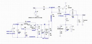
I have done a bit more on the independent bias voltage supply, and refined the design. So follow this new schematic. The voltage regulator is a TL783. The diodes remain 1N4002. Modifications to the pcb are shown. One cut to a trace and four cuts to radial spokes at the ground plane are required. C8 needs polarity reversal and a wired connection
Attachments


- Home
- Amplifiers
- Pass Labs
- 25W Single Ended Hammond 193V Choke Loaded 2SK180 L'Amp