Hi Folks
I was ask to update this thread after Elwood625 help me select the Aleph J circuit for the SemiSouth SJEP120R100 that was gift to me in this thread.
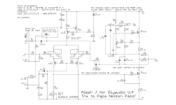
In post#82 it was mentioned that R18 can be jumped and also R24 value should be experimented with. What will be the best solution to measure the current at the output stage ? Measure the voltage across R16 ? or place an ammeter where R18 used to be and place a switch to jumped it when done measuring the bias ? For R24, should that be changed to a 2K pot ? Also, is the best solution to turn on "thump" is to use this soft start circuit ?
Thanks in advance for any help
I was ask to update this thread after Elwood625 help me select the Aleph J circuit for the SemiSouth SJEP120R100 that was gift to me in this thread.
In post#82 it was mentioned that R18 can be jumped and also R24 value should be experimented with. What will be the best solution to measure the current at the output stage ? Measure the voltage across R16 ? or place an ammeter where R18 used to be and place a switch to jumped it when done measuring the bias ? For R24, should that be changed to a 2K pot ? Also, is the best solution to turn on "thump" is to use this soft start circuit ?
Thanks in advance for any help
Attachments


- include 1Meg from neg input to GND, that 1uF cap still needs somewhere to be bled to, in all circumstances, just for giggles if not all practical reasons
-instead of zener-BC critter CCS - use ring of two CCS; on my side of pond, usual parts for that combo are BC556 and BD140; better sleep, wider green, lily must be gilded
-put 5V6 zener across C-E of small bjt in Aleph CCS; see enclosed pdf, origin A. W. Newby
-trimpot in 2SJ drain is way too big; 2SJ having 4mA Iq, SS needs no more than 1V5 to be fully open; depending of SS source resistance (yes or not) make your calc; pretty much 270R as fixed resistor, in series with 200R trimpot is all you need
I'm sure there are more things, but - first morning coffee, yadayada
Attachments
Zen Mod thanks for the article. This is my first foray in building a DIY Solid state amp, I have built tube SE and OTL from scratch in the past. Building this is a great learning opportunity for me.
1. I will put a high value resistor at the input of the 10uf cap.
2. The change of CCS for the Toshiba Jfet to the "Ring of 2", I had Bard AI explain how that works. I will implement that change later. Since I already have the parts for the DiyAudio store Aleph J board.
3. Trim pots(R7) for Toshiba 2SJ, I used the schematic on Post # 81 as the base for my hand draw schematic; I notice that the original schematic (DIY Store) had a 1K resister in parallel with the 2K pot. Which essentially making it 666 ohm pot, which is much closer to the value that is being suggested. It had a added benefit of protecting the circuit if the pot goes bad. I will put the 1K resistor in parallel .
4. Since I going to omit R18 the source resistor, What will be the best solution to measure the current at the output stage ? Measure the voltage across R16 ? or place an ammeter where R18 used to be and place a switch to jumped it when done measuring the bias ? For R24, should that be changed to a 2K pot ? Also, is the best solution to turn on "thump" is to use this soft start circuit ?
Measure the voltage across R16 ?
setting pretty much - one DVM to observe voltage sag across (your) R16 so calc sez what's Iq, and second DVM from output to GND, to observe output DC Offset
inputs shorted to GND, no load at output
Best solution is:Also, is the best solution to turn on "thump" is to use this soft start circuit ?
1 - Turn on: First the source, CD/DAC and/or phono preamp, then line stage, next active crossover and at last the amplifier.
2 - Turn off: Reverse it, amplifier first, then active cross over, line stage and finally source (s).
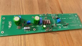
Thanks to a fellow board member, I was able to build a pair of the boards done by RainfallSky. These were an easy build, I was just taking my time.
My choices were IRFP048 in the upper position and FQH44N10 in the lower. The 44N10 part is my take on good sounding, yet hard to find devices. I save these for special builds. I tweaked the input stage a little to accommodate the higher voltage supply. 10V zener at D1, 1.1k at R8, 200 Ohm at R0, 6.19k at R6. C5 is 10pF because that is what I had, but it seems to be a good choice.
The chassis is the same one that I used for my F6 JFet boards. I upgraded the power transformer to the Antek AS-4220 and managed to get 25.6V at the power rails. This is one of the few amps of mine that uses a shared transformer and main filter board for both channels. I added a set of 80 uF motor run caps next to each channel to help out. This seems to have worked very well. I set bias current to 1.6A which is close to the limit of what the Deluxe 4U Chassis can handle, about 81W per side considering the voltage.
This build is dead silent, as in no discernible hum at the speakers. Better than what I recall from the F6 build that was the previous resident.
Initial play had somewhat startling clarity, on the side of extra emphasis in the upper frequencies. This is common for brand new channel boards, and did smooth out a little by the end of the first day. Bass dynamics and extension are quite impressive, putting the qualities of the big Vandersteens in my listening space to good use. Imaging is also excellent, making those big speakers completely disappear. The soundstage is decidedly forward for the time being. I expect it will eventually reside in a comfortable middle with further playing time.
This is an enjoyable variant on the Aleph J. I have wanted to try the FQH44N10 in this amp since I started using it in the F6. The Aleph J SS PCBs are well executed and seem to be a good platform for experimentation with alternate FETs.
always great to learn from you ZM
and what advantage to cascade each J74 ?
I am referring to your bablefish j
2 extra bd140 are fine but is there a way to avoid the led string and the mmbf5486 CCS to drive the led string?
I would like to keep it as simple as possible and I don't have mmbf5486 on hand
and what advantage to cascade each J74 ?
I am referring to your bablefish j
2 extra bd140 are fine but is there a way to avoid the led string and the mmbf5486 CCS to drive the led string?
I would like to keep it as simple as possible and I don't have mmbf5486 on hand
Patience finally pays off ")
This version of the Aleph J needs plenty of time to run in. Mine has over 60 hours on it now. The clarity and detail are still amazing, but not to excess. Overall tone is well balanced and without the high frequency emphasis that was present earlier. The clarity offers deeper insight into vocals and hall ambience.
I used high quality audio components, as I typically do. This amp will benefit from the best you can find. Nichicon FG series to start, or KZ if you can find some. Elna RFS (Silmic II) or ROA (cerafine) are great if you can find them. If you don’t mind searching for Shinkoh or Takman resistors, that effort would not be wasted.
Hi Tungsten, you make me want to finish this amp asap! I’m almost finished, I just need to fit the amp boards into the chassis!
Also I still have a pair of Rainfallsky’s boards if anyone interested!
I have a question for you, my simulation in spice tell me that for about 1.6 amp bias, the bias pot is somewhere near 13k. Can you confirm that? If that’s the case I will use a 20k or 50k trimpot instead of the 100k on the schematic. Also do you drive your amp balanced or unbalanced? What do you have at the C1 position? Thank you!
Hubert
Attachments

- Home
- Amplifiers
- Pass Labs
- Semisouth Aleph J?