I see the logic where the speaker cable itself benefits from the zobel, interestingly we are hoping that the speaker cable , the few inches coupling to the amplifier has more of an inductive rather than capacitive characteristic as such the amplifier will see a reasonable high frequency load via the zobel and thus reduce ringing, lets call it assumptions until something breaks. Yes your right in wanting it on that side. Lets assume that the output devices are tempted to self oscillate, at that point you want a high impedance high frequency load as seen from the jittery output devices, and especially if already using base resistors that's a good sign you want it on the other side. At that point also you start viewing the high frequency feedback capacitor across the feedback resistor with suspicion and especially if you are using miller compensation. By now your getting jittery still and want to put a zobel across both inverting and non inverting inputs or on both collectors of the LTP, fun stuff reallyNice result 👍. I’d put the Zobel on the amp side of the output coupling inductor though. Placing it after the inductor acts as a termination for the cabling<>speaker cable load but does not present the amplifier output with a fiat load impedance over frequency which is what it does if placed before the L. See Self and Cordell for more detail
Last edited:
There are two separate things going on here. The Zobel on the speaker side of the inductor will help damp the ringing all amplifiers driving a RLC load (ie every cable<>speaker combo you care to imagine) see at the amplifier output terminals. Some practitioners don’t see this as a particularly important issue - but that of course is a design choice.
The Zobel on the amplifier side of the inductor is there to ensure that in combo with the [output L + damping resistor + the cable + the speaker], the amplifier lumped load looks broadly resistive all the way out to 2-3 MHz. That’s what prevents HF parasitic oscillation in the OPS, assuming you have taken care of decoupling etc and the amp is properly compensated. This happens because in many cases the output devices ‘see’ a negative resistance in their base, which, when the output load is reactive, causes oscillation (see i.a.o. Dennis Fuchs). You get this with both EF and CFP OPSs.
The primary destruction mechanism in OPS HF parasitic oscillation is not excess current through the load- about 4-6 ohms in most cases - but cross conduction in the output devices which causes very high currents to flow between the rails through the output devices.
Mark Tillotson - You are mis-interpreting my post. I will use more words.
Zener diode X1 can be replaced by regular forward-biased diodes or a clamping diode. Its purpose is to limit excursion so that base drive to X5 and X6 won't collapse. Regular diodes generate less noise. This is better than using a noisy zener and letting feedback "fix" the noise.
The same argument can be applied to X7 and X9.
All the other zeners already have bypass capacitors.
My point is not to avoid feedback but rather to design a good circuit.
Ed
He he he Bonsai, very convincing explanation, will respond laterThere are two separate things going on here. The Zobel on the speaker side of the inductor will help damp the ringing all amplifiers driving a RLC load (ie every cable<>speaker combo you care to imagine) see at the amplifier output terminals. Some practitioners don’t see this as a particularly important issue - but that of course is a design choice.
The Zobel on the amplifier side of the inductor is there to ensure that in combo with the [output L + damping resistor + the cable + the speaker], the amplifier lumped load looks broadly resistive all the way out to 2-3 MHz. That’s what prevents HF parasitic oscillation in the OPS, assuming you have taken care of decoupling etc and the amp is properly compensated. This happens because in many cases the output devices ‘see’ a negative resistance in their base, which, when the output load is reactive, causes oscillation (see i.a.o. Dennis Fuchs). You get this with both EF and CFP OPSs.
The primary destruction mechanism in OPS HF parasitic oscillation is not excess current through the load- about 4-6 ohms in most cases - but cross conduction in the output devices which causes very high currents to flow between the rails through the output devices.
Specifically in your implementation of the circuit, this is just not normal. The reason is simple - you have a quasi-complementary output stage, the high signal rise rate allows you to make their operation more linear, and the location of Zobel circuit at the amplifier output before the LR coil will protect the feedback circuit from the capacitive nature of the speaker load at a frequency of 20 kHz and higher... Here if your output stage operated in class A, then the inductance of the cable to the speaker system would be more important.Its fine as is due to the resistor across inductor.
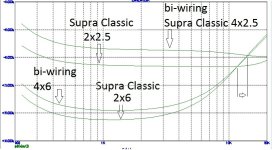
I conducted some tests of speaker cables, namely the influence of their parameters and footage on the frequency response of the amplifier, so I know what I’m writing about, in the attachment, a test of cables from a Swedish manufacturer. The attempt to connect the Zobel circuit at the output of the amplifier and the cable to the speaker systems has long ago lost its relevance, because The quality of these same wires has increased.I’d put the Zobel on the amp side of the output coupling inductor though. Placing it after the inductor acts as a termination for the cabling<>speaker cable load but does not present the amplifier output with a fiat load impedance over frequency which is what it does if placed before the L. See Self and Cordell for more detail
Attachments
All this takes us back to The Leach Amp (Note C10,C8,C9). Where should we close the global feedback loop, before or after OPS? I know Papa is watching keenly he he he and has just reached for his glass of wine, class A , non switching, 1 stage, 2 stage , 3 stage ? Bonsai see what you started

I don't quite understand what the connection is... ok, Marshall Leach, there are a lot of bugs in the attachment that significantly affect the quality of sound playback. For example, a diode matrix is unnecessary for temperature stability of the output stage; you could simply increase the current through the multiplier divider and everything would become quite stable.All this takes us back to The Leach Amp (Note C10,C8,C9).
But this does not in any way affect the installation of the Zobel circuit, its main purpose is to increase the load linearity at high frequencies at the negative feedback output point.
P.S. If you are interested in modding this version of the Marshall Leach circuit, then I did it for +/- 60 volt power. I can post it for your reference.
Last edited:
C8 and C9 excluding the driver and output stages from the global feedback loop at high frequencies was a bad idea, IMO.
I'm sorry, but you misinterpret this decision. in Marshall Leach’s scheme, C8 just worsens stability due to its integrating action, and C9 is installed to compensate for the negative effect of installing C8. Negative feedback from the amplifier's power output point must be provided exclusively by linear elements.
Last edited:
@Hennady Kovalsky - We are saying the same thing. I have put a lot of effort into avoiding the pitfalls of the "Low TIM" design style.
Ed
Ed
This is very good, and then you know for sure that the Zobel circuit is part of the frequency progressive correction and should be placed at the point in the amplifier where the out impedance increases at high frequencies. If it is necessary to compensate for the influence of a large-section acoustic cable, you can install a second Zobel after the LR chain.@Hennady Kovalsky - We are saying the same thing. I have put a lot of effort into avoiding the pitfalls of the "Low TIM" design style.
HenK
This is good only in case that we make the amplifiers for ourselves onlyI made sure that my amplifier was stable without a load. I solved the excess load capacitance problem by not buying high-capacitance cables or speakers.
") .
.But it would not make a universal, load independent, unconditionally stable amplifier, which is a must if we make amplifiers for sale
.I made sure that my amplifier was stable without a load.
It is difficult to understand this comment, because... the absence of load should reduce the gradient of phase change with increasing frequency, i.e. stability in this case will increase anyway.
If you look at my test graphs of the influence of acoustic wires, then their capacitive nature in the frequency band 20Hz - 20kHz can be completely eliminated when connecting with bi-wiring. The linearity of the amplifier before the NFB coating is also important.I solved the excess load capacitance problem by not buying high-capacitance cables or speakers.
HenK
If Leach was worried about the amplifier ringing with rhdcRLC speaker load then his Zobel serves its purpose. However, his very nice amplifier falls short by not including a Zobel on the amplifier side of the output inductor.
See Self and Cordell.
See pages 19-23 in the link below. Although this mainly concerns itself with small signal buffers, the theory applies to power buffer stages as well, and especially in the case of EF2/3 and CFP.
https://worldradiohistory.com/UK/Wireless-World/00s/Electronics-World-2003-10-S-OCR.pdf
- Home
- Amplifiers
- Solid State
- Symphony Amplifier